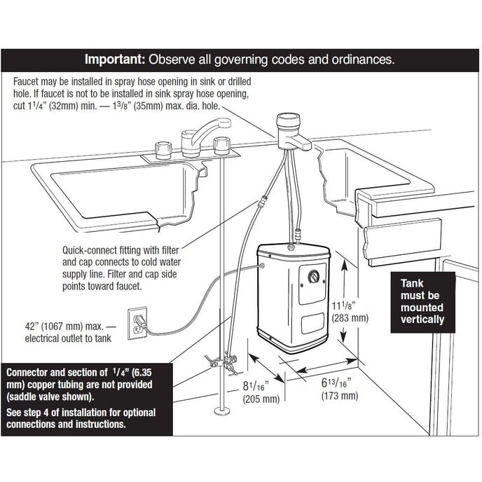
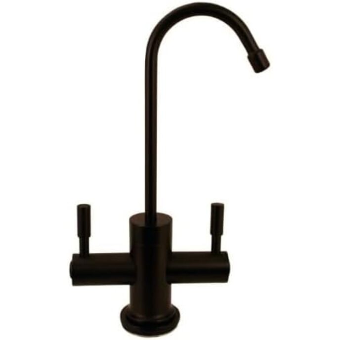
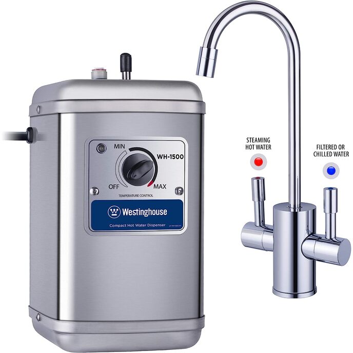
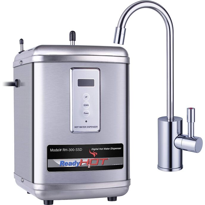
*** See UPDATES below *** ORIGINAL REVIEW This unit, manufactured in December 2014, was bought on March 2015 to replace the second InSinkErator dispenser to become corroded in less than 2 years of use. It arrived well packaged and had all the manufacturer's components; both the Coronado faucet and the tank are nice looking, and the flexible hoses are clearly tagged. Given that under the sink we already had attached to the cold water pipe a T-connector with safety valve for 1/4" tubing (as well as a GFCI receptacle for an electric line capable of supporting the operation of both the dishwasher and this 11W dispenser), my first impression was that it would be a very quick job. I was mistaken. One long look at the enclosed manual (Revision J [English] -- the PDF file from the Amazon webpage link to the user manual is Revision G) was enough to bring a feeling of impending doom. It was not that it had been written in Taiwan's Cantonese and then poorly translated to English with a web engine; actually, the printed text is often well written, with plenty of figures and highlighted text boxes. The problem was that the instructions did not seem to match the hardware. After some deliberation and checking reviews, particularly the images uploaded by reviewers, it was clear the manufacturer did not include all the necessary pieces for an easy installation, and that a trip to a local hardware store was needed. The INPUT to the tank first has a 3/8" braided hose but the water must first go through a 1/4" quick-connect fitting with a coarse filter, so one needs pieces of both 3/8" and 1/4" pipe. The hose connects to the tilt valve of the faucet; from there the water goes through the second braided hose, which has a 1/4" compression fitting, and then the second quick-connect fitting (without a filter inside) to reach the tank. Given what was available at the store I came up with the following system for the input, shown in Fig. A : [1] a short 1/4" copper pipe (attached on one end to the T-connector's valve) connects to [2] the 1/4" quick-connect fitting filter; this connects to [3] another short piece of 1/4" pipe that attaches to [4] a 1/4"-to-3/8" compression adapter that connects to [5] a short piece of 3/8" pipe whose other end connects to [6] the braided, 3/8" hose via a compression fitting; the hose connects to the the faucet's valve. (Note: a 1/4 to 3/8 inch adapter was not available in the store; it was built by combining pieces from different adapter parts.) Figure B shows that : [1] the other braided hose, which comes from the faucet's valve, attaches to [2] a short piece of 1/4" copper pipe via a compression fitting; the pipe connects to [3] the second quick-connect fitting, which connects to [4] the 1/4" tank inlet pipe extruding from one of the corners on top of the tank. The OUTPUT of the tank, also shown in Fig. B, needs no additional parts : the [5] 3/8" metal tube extruding from the center of the tank's top is attached to a metal hose connector whose nipple receives one end of [6] the neoprene tube; its other end attaches to the nipple at the end of a threaded tube of the faucet (which serves to mount the faucet on sink). Soaking the neoprene tube in warm water facilitates its mounting on the metal nipples. The tools I used, shown in Fig. C, were : [1] an adjustable wrench; [2] a (bent) bike cone wrench; [3] a pipe cutter for [4] 1/4" and 3/8" copper pipe; and [5] a knock-out punch. The cone wrench, which fitted the provided mounting nut, was used to mount the faucet on the sink, instead of a more expensive faucet wrench; it was bent to fit in the tight space at the mounting point. The punch was used to enlarge an existing 1" mounting hole to a three-leaf shamrock format matching the tubing arrangement at the bottom of the faucet. Only small pieces of additional tubing are needed, so I bought the shortest pieces on sale of 3/8" and 1/4" copper pipe. I have taken one star because obtaining and then putting together the additional parts for the water input took a considerable amount of time. Once all tank connections were made the faucet mounted, there were no leaks whatsoever. The tank MUST be filled with water before power is applied to the unit; else, the self-resetting thermal fuse of the heater will interrupt the circuit for about 30 minutes. The thermostat control dial on the tank makes it very easy to adjust water temperature. A negative aspect of the unit is that the position of the faucet's spout can be changed too easily, even by lightly bumping into it. This is a problem since the hand could be burned if the spout were directed at the handle lever. Also, unless water pressure is reduced, the water is dispensed with force (sometimes in three divergent jets, instead of a single jet) and one may get splashed with hot drops. I have taken another star because of this potential risk. The manufacturer should carefully revise the installation instructions (which are not only confusing but often also too busy), add an aerator to reduce the force of the water jet and avoid divergent multiple jets, and include a few short pieces of 1/4"and 3/8" tubing and an adapter to facilitate installation. UPDATE - April 2015 After several instances of people getting splashed with hot water I decided to install the aerator the manufacturer ought to have installed. For that I bought an aerator repair kit METAL MESH. I unscrewed the tip of the faucet, removed its white plastic tubular insert (it has a black O-ring facing the faucet's tube), and then I cut the mesh using the white plastic insert as a round cutting guide. I placed the mesh in the end of the faucet's tip, replaced the plastic insert in the tip, and screwed the tip on the faucet's tube. There is little or no splashing now. UPDATE - October 2016 After some 19 months of use, the dispenser developed a perforation in a plastic component (see below) that produced a water LEAK every time the device was used. Because of the geometry of the sink cabinet where the body of the dispenser had been installed, the leaks were not immediately detected and the water completely damaged the wood board that serve as the floor of the sink cabinet. I decided to look inside the device to find what part had failed and see if a replacement part could solve the problem. Figure D shows the metal enclosure after removing the dispenser as seen from the front side. The red arrow points to the oxidized spot on the back of the enclosure that was splashed by the leaking water from the device. Figure E shows the actual body of the hot-water dispenser as seen from the back side. The red frame (and the magnified view of this area in the inset) shows a circular opening in a squarish flat chamber made of white plastic on the back side of the device from where the water leaked out. This hole --located next to a partial hole produced by some manufacturing error that almost perforated the chamber, and above a heavily oxidized screw-- is a normal part of the dispenser, where it seems to help equilibrate pressure inside this chamber. The leak originates from a plastic (silicone?) membrane inside the chamber, which one of the FAQ answers in the manufacturer's website describes as "bladder that allows the water to be vacuumed back into the unit." Figure F shows the chamber (isolated from the body) after the screws that secure its halves were removed. Between these halves, like the contents of a sandwich, is the membrane, which can be barely seen on top of the right half in the figure due to the low contrast between the plastic of the chamber and of the membrane. Figure G shows the membrane more clearly against a dark background; the red circle encloses the slanted rip in the membrane that produced the leaks. (The central white square-like stain is actually embedded in the plastic membrane.) Since its warranty is of only one year, I will contact the manufacturer, Anaheim Manufacturing Company, which is a division of Moen Inc., to se